Buses
A bus is a set of electrical terminals sharing a location. It owns the network's voltage variables and is where Kirchhoff's current law is enforced. Parts 1–5 state the foundational (physics) model; part 6 records how BMOPFTools realises it. Symbols are defined in Notation.
1. Data model
A bus is an entry of the top-level bus object, keyed by its string ID $i$.
| Field | Type | Unit | Req. | Description |
|---|---|---|---|---|
terminal_names | string[] | – | ✔ | Ordered terminal names $\textcolor{purple}{\mathbf{N}_i}$ |
perfectly_grounded_terminals | string[] | – | Terminals fixed to $0\text{ V}$ | |
v_min, v_max | number[] | V | Phase-to-ground magnitude bounds, one per phase terminal | |
vn_max | number | V | Neutral-to-ground magnitude cap | |
vpn_min, vpn_max | number[] | V | Phase-to-neutral magnitude bounds, one per phase | |
vpp_min, vpp_max | number[] | V | Phase-to-phase magnitude bounds, one per phase pair | |
vpos_min, vpos_max | number | V | Positive-sequence magnitude bounds (three-phase buses) | |
vneg_max | number | V | Negative-sequence magnitude cap (lower bound is always 0) | |
vzero_max | number | V | Zero-sequence magnitude cap (lower bound is always 0) |
All bound fields are optional: an absent bound means the corresponding limit is not enforced.
2. Input symbols
| Field | Symbol | Notes |
|---|---|---|
terminal_names | $\textcolor{purple}{\mathbf{N}_i}$ | stacking order for all bus vectors |
v_min, v_max | $\textcolor{red}{\mathbf{U}^{\min}_i},\ \textcolor{red}{\mathbf{U}^{\max}_i}$ | per phase, to ground |
vn_max | $\textcolor{red}{U^{\max}_{i,n}}$ | scalar, neutral to ground |
vpn_min, vpn_max | $\textcolor{red}{\mathbf{U}^{Y,\min}_i},\ \textcolor{red}{\mathbf{U}^{Y,\max}_i}$ | per phase, to neutral |
vpp_min, vpp_max | $\textcolor{red}{\mathbf{U}^{\Delta,\min}_i},\ \textcolor{red}{\mathbf{U}^{\Delta,\max}_i}$ | per phase pair |
vpos_min, vpos_max | $\textcolor{red}{U^{1,\min}_i},\ \textcolor{red}{U^{1,\max}_i}$ | positive-sequence magnitude |
vneg_max, vzero_max | $\textcolor{red}{U^{2,\max}_i},\ \textcolor{red}{U^{0,\max}_i}$ | negative-/zero-sequence caps (lower bound 0) |
3. Variables
Each terminal $p\in\mathcal{N}_i$ has a complex voltage-to-ground $\textcolor{blue}{U_{i,p}}$, stacked into the bus voltage vector
\[\textcolor{blue}{\mathbf{U}_i} = \big[\,\textcolor{blue}{U_{i,p}}\,\big]_{p\in\mathcal{N}_i} \in \mathbb{C}^{|\mathcal{N}_i|}.\]
Ground is the common $0\text{ V}$ reference, so these are the only quantities needed to describe the bus's electrical state.
4. Equality constraints
Perfect grounding
A perfectly grounded terminal is pinned to the ground reference:
\[\textcolor{blue}{U_{i,p}} = 0 \qquad \forall\, ip \in \mathcal{M}^{\emptyset}.\]
Voltage source (reference bus)
The voltage source $s$ at bus $i$ fixes its phase terminals to the reference magnitude/angle and its neutral to ground:
\[\textcolor{blue}{U_{i,p}} = \textcolor{red}{U^{s}_{i,p}} = \textcolor{red}{|U^{s}_{i,p}|}\,\textcolor{brown}{\angle}\,\textcolor{red}{\theta^{s}_{i,p}}, \qquad \textcolor{blue}{U_{i,n}} = 0.\]
The source also injects a free slack current into KCL, making this the power-flow reference bus (detailed on the future Voltage sources page).
Kirchhoff's current law
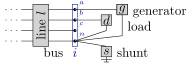
At each terminal, the currents of all incident elements sum to zero (sign convention: into the bus positive):
\[\underbrace{\sum_{\ell ij\in\mathcal{T}^{L}}\!\textcolor{blue}{\mathbf{I}_{\ell ij}}}_{\text{lines}} + \underbrace{\sum_{xij\in\mathcal{T}^{X}}\!\textcolor{blue}{\mathbf{I}_{x ij}}}_{\text{transformers}} + \underbrace{\sum_{wij\in\mathcal{T}^{W}}\!\textcolor{blue}{\mathbf{I}_{w ij}}}_{\text{switches}} + \underbrace{\sum_{di\in\mathcal{C}^{D}}\!\textcolor{blue}{\mathbf{I}_{d}}}_{\text{loads}} - \underbrace{\sum_{gi\in\mathcal{C}^{G}}\!\textcolor{blue}{\mathbf{I}_{g}}}_{\text{generators}} + \underbrace{\sum_{hi\in\mathcal{C}^{H}}\!\textcolor{blue}{\mathbf{I}_{h}}}_{\text{shunts}} = \mathbf{0}.\]
This holds at every terminal except where the bus is voltage-source-fixed or grounded (there the terminal voltage is set directly, and the balancing current is a free variable rather than a constraint).
5. Inequality constraints
Cartesian variable bounds
None. The physics places no box on the rectangular components of $\textcolor{blue}{\mathbf{U}_i}$; voltage is constrained only by the engineering bounds below and by grounding/source fixing. A box on the real/imaginary parts would impose an axis-aligned magnitude-and-angle limit with no operational meaning.
Engineering bounds
Applied at ungrounded, non-source phase terminals (the neutral is excluded from phase bounds — its voltage is set by physics, not operational limits).
Phase-to-ground magnitude. With $\textcolor{red}{U^{\min}_{i,n}}=0$ and the neutral's upper bound supplied by vn_max:
\[\textcolor{red}{\mathbf{U}^{\min}_i}\!\circ\textcolor{red}{\mathbf{U}^{\min}_i} \ \le\ \textcolor{blue}{\mathbf{U}_i}\circ\textcolor{blue}{\mathbf{U}_i}^{*} \ \le\ \textcolor{red}{\mathbf{U}^{\max}_i}\!\circ\textcolor{red}{\mathbf{U}^{\max}_i}.\]
Neutral-to-ground cap (vn_max, only when the neutral floats):
\[|\textcolor{blue}{U_{i,n}}| \le \textcolor{red}{U^{\max}_{i,n}} \ \Longleftrightarrow\ \textcolor{blue}{U_{i,n}}\,\textcolor{blue}{U_{i,n}}^{*} \le (\textcolor{red}{U^{\max}_{i,n}})^2.\]
Phase-to-neutral magnitude. With $\textcolor{blue}{\mathbf{U}^{Y}_i} = \textcolor{red}{\mathbf{M}^{Y}}\,\textcolor{blue}{\mathbf{U}_i}$ (or $\textcolor{blue}{\mathbf{U}_i}[\mathcal{P}]$ when the neutral is grounded):
\[\textcolor{red}{\mathbf{U}^{Y,\min}_i}\!\circ\textcolor{red}{\mathbf{U}^{Y,\min}_i} \ \le\ \textcolor{blue}{\mathbf{U}^{Y}_i}\circ(\textcolor{blue}{\mathbf{U}^{Y}_i})^{*} \ \le\ \textcolor{red}{\mathbf{U}^{Y,\max}_i}\!\circ\textcolor{red}{\mathbf{U}^{Y,\max}_i}.\]
Phase-to-phase magnitude. With $\textcolor{blue}{\mathbf{U}^{\Delta}_i} = \textcolor{red}{\mathbf{M}^{\Delta}}\,\textcolor{blue}{\mathbf{U}_i}[\mathcal{P}]$:
\[\textcolor{red}{\mathbf{U}^{\Delta,\min}_i}\!\circ\textcolor{red}{\mathbf{U}^{\Delta,\min}_i} \ \le\ \textcolor{blue}{\mathbf{U}^{\Delta}_i}\circ(\textcolor{blue}{\mathbf{U}^{\Delta}_i})^{*} \ \le\ \textcolor{red}{\mathbf{U}^{\Delta,\max}_i}\!\circ\textcolor{red}{\mathbf{U}^{\Delta,\max}_i}.\]
Symmetrical-component magnitudes (three-phase buses). The sequence voltages use phase-to-neutral inputs when a neutral floats, phase-to-ground otherwise:
\[\textcolor{blue}{\mathbf{U}^{\text{sym}}_i} = \textcolor{brown}{\mathbf{F}}\,\textcolor{blue}{\mathbf{U}^{Y}_i} = \begin{bmatrix}\textcolor{blue}{U^{0}_i}\\ \textcolor{blue}{U^{1}_i}\\ \textcolor{blue}{U^{2}_i}\end{bmatrix}, \qquad \begin{aligned} (\textcolor{red}{U^{1,\min}_i})^2 &\le \textcolor{blue}{U^{1}_i}(\textcolor{blue}{U^{1}_i})^{*} \le (\textcolor{red}{U^{1,\max}_i})^2,\\ \textcolor{blue}{U^{2}_i}(\textcolor{blue}{U^{2}_i})^{*} &\le (\textcolor{red}{U^{2,\max}_i})^2,\qquad \textcolor{blue}{U^{0}_i}(\textcolor{blue}{U^{0}_i})^{*} \le (\textcolor{red}{U^{0,\max}_i})^2. \end{aligned}\]
Only the positive sequence carries a lower bound.
Intra-bus angle difference. For each phase pair $(p,q)$, with a nominal offset $\Delta=\textcolor{red}{\theta^{\text{nom}}_{i,q}}-\textcolor{red}{\theta^{\text{nom}}_{i,p}}$ and $\textcolor{blue}{z}=\textcolor{blue}{U_{i,p}}^{*}\textcolor{blue}{U_{i,q}}\,e^{-\textcolor{brown}{j}\Delta}=c+\textcolor{brown}{j}s$:
\[\tan(\textcolor{red}{\theta^{\Delta,\min}_i})\, c \ \le\ s \ \le\ \tan(\textcolor{red}{\theta^{\Delta,\max}_i})\, c,\]
which bounds the angle between the two terminals (faithful while $c>0$, i.e. the centred deviation stays within $\pm\pi/2$).
6. Implementation in BMOPFTools
Realisation
- Rectangular variables. Each $\textcolor{blue}{U_{i,p}}$ is two real variables
vr[(i,p)],vi[(i,p)](its real and imaginary parts), declared free invariables.jl:_add_voltage_variables!. No box is set — matching no cartesian bound in part 5. - Grounding is
fix(vr,0); fix(vi,0)in the same function. A free ground-injection currentcr_gnd/ci_gnd(_add_ground_variables!) is added at each grounded terminal so current can flow into earth there. - Source fixing is
fix(vr, |U|·cos θ); fix(vi, |U|·sin θ)insource.jl:_add_source_constraints!. - KCL is not stamped as the single vector equation of part 4. Instead each incident element adds its signed contribution into a per-terminal accumulator $(\kappa^{\Re}_{i,p},\kappa^{\Im}_{i,p})$ (
bus.jl:_init_kcl,_kcl_add!), and the real and imaginary parts are set to zero separately, $\kappa^{\Re}_{i,p}=0,\ \kappa^{\Im}_{i,p}=0$ (bus.jl:_add_kcl_constraints!). This is the same equation, accumulated incrementally. Grounded terminals keep their KCL equation, balanced by the ground-injection current. - Engineering bounds are stamped as
vr^2 + vi^2-style quadratics inbus.jl:_add_voltage_bounds!(phase-to-ground) and_add_bus_limit_constraints!(vn_max, phase-to-neutral, phase-to-phase, symmetrical components, angle). The Fortescue transform is applied as an explicit real expansion of $\textcolor{brown}{\mathbf{F}}$ rather than a matrix multiply.
Source map
| Constraint | Code location |
|---|---|
| Voltage variables / grounding | variables.jl:_add_voltage_variables! |
| Ground-injection current | variables.jl:_add_ground_variables! |
| Source fixing | source.jl:_add_source_constraints! |
| KCL (accumulator + equality) | bus.jl:_init_kcl, _kcl_add!, _add_kcl_constraints! |
| Phase-to-ground bounds | bus.jl:_add_voltage_bounds! |
vn_max, vpn, vpp, sym, angle | bus.jl:_add_bus_limit_constraints! (blocks a–e) |
Reconciliation notes (data model)
The schema and the OPF solver now agree: sequence bounds are the four scalar fields vpos_min, vpos_max, vneg_max, vzero_max. Only the positive sequence carries a lower bound; the negative- and zero-sequence lower bounds are always 0. This replaces the earlier single array pair vsym_min/vsym_max.
The intra-bus angle bound uses fields va_diff_min, va_diff_max and the nominal-offset vector va_nom, and the PDF math model defines the constraint — but none of these fields are in the schema's bus properties. Add them (units: radians) so the constraint the solver already enforces is expressible in conformant data.